
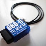

Freematics OBD-II Adapter for Arduino
This product works as a vehicle OBD-II data bridge for Arduino, providing OBD-II data access with Arduino library as well as power supply (converted and regulated from OBD-II port) for Arduino and its attached devices. The product and its library are compatible with all Arduino series including all 8-bit AVR based Arduino as well as 32-bit Arduino DUE and Yún.
Features
- Directly pluggable into vehicle’s OBD-II port
- Serial data interface (UART or I2C)
- High efficiency DC-DC module for 5V/3.3V DC output up to 2A
- Supporting CAN bus and KWP2000 protocols
- Fast (up to 100Hz) access to all OBD-II PIDs available in vehicle ECU
- Embedded 3-axis accelerometer, 3-axis gyroscope and temperature sensors
- Extendable and actively maintained Arduino library and example sketches provided
Freematics OBD-II Adapter MK2 has an additional MPU6050 module built inside, which provides accelerometer, gyroscope and temperature sensor all accessible via the extended ELM327 AT command-set. Accelerometer can be used for measuring car’s acceleration and steering G-force. Gyroscope can be used for measuing car’s orientation without GPS. When the adapter is plugged and locked in the car’s OBD-II port, the MPU6050 module inside the case will always stay static to the car body, so the sensor data can reflect the movement of the car accurately.
Compatibility
The adapter stays plugged into the OBD port usually located under the steering column or slightly to the left of it. It supports the following countries and year of manufacture:
- United States (Gas) 1996+
- United States (Diesel) 2004+
- Canada (Gas) 1998+
- Europe + UK (Gas) 2001+
- Europe + UK (Diesel) 2004+
- Australia + NZ (Gas/Diesel) 2006+
Vehicles made prior to the dates above may still be OBD-II certified. To check if your vehicle is OBD-II certified, open your hood and find the sticker that looks like this:
Following vehicle protocols are supported.
- CAN 500Kbps/29bit
- CAN 250Kbps/29bit
- KWP2000 Fast
- KWP2000 5Kbps
Freematics OBD-II Adapter is compatible with both 5V and 3.3V systems. VCC is 5V which can power all range of Arduino boards.
Getting Started
The adapter stays plugged into the OBD port usually located under the steering column or slightly to the left of it.


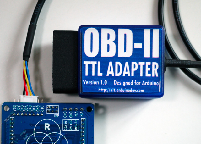
A cable comes out from the adapter and splits into two 2-pin connectors, including power lines (VCC/GND)and data lines (Rx/Tx). They can be connected to Arduino with onboard breakout pins or breakout shield. Your Arduino device will look tidy in car with only one cable.
Power Lines:
- Red: VCC (connecting to Arduino’s VCC)
- Black: GND (connecting to Arduino’s GND)
Data Lines
- White: Rx (connected to Arduino’s serial Tx)
- Green: Tx (connected to Arduino’s serial Rx)
The Library
A dedicated Arduino library is developed and maintained regularly, providing a set of easy-to-use APIs to retrieve real-time data from a vehicle.
Here is an example code of a simplest engine RPM indicator, which uses the pin 13 LED (built in every Arduino board) to indicate whether the engine is above 3000 rpm.
#include <Wire.h>
#include <OBD.h>

COBD obd; /* for Model A (UART version) */

void setup()
{
  // we'll use the debug LED as output
  pinMode(13, OUTPUT);
  // start communication with OBD-II adapter
  obd.begin();
  // initiate OBD-II connection until success
  while (!obd.init());
}

void loop()
{
  int value;
  // save engine RPM in variable 'value', return true on success
  if (obd.read(PID_RPM, value)) {
    // light on LED on Arduino board when the RPM exceeds 3000
    digitalWrite(13, value > 3000 ? HIGH : LOW);
  }
}
Most commonly use PIDs are defined in OBD library as followings.
Engine
- PID_RPM – Engine RPM (rpm)
- PID_ENGINE_LOAD – Calculated engine load (%)
- PID_COOLANT_TEMP – Engine coolant temperature (°C)
- PID_ENGINE_LOAD – Calculated Engine load (%)
- PID_ABSOLUTE_ENGINE_LOAD – Absolute Engine load (%)
- PID_TIMING_ADVANCE – Ignition timing advance (°)
- PID_ENGINE_OIL_TEMP – Engine oil temperature (°C)
- PID_ENGINE_TORQUE_PERCENTAGE – Engine torque percentage (%)
- PID_ENGINE_REF_TORQUE – Engine reference torque (Nm)
Intake/Exhaust
- PID_INTAKE_TEMP – Intake temperature (°C)
- PID_INTAKE_PRESSURE – Intake manifold absolute pressure (kPa)
- PID_MAF_FLOW – MAF flow pressure (grams/s)
- PID_BAROMETRIC – Barometric pressure (kPa)
Speed/Time
- PID_SPEED – Vehicle speed (km/h)
- PID_RUNTIME – Engine running time (second)
- PID_DISTANCE – Vehicle running distance (km)
Driver
- PID_THROTTLE – Throttle position (%)
- PID_AMBIENT_TEMP – Ambient temperature (°C)
Electric Systems
- PID_CONTROL_MODULE_VOLTAGE – vehicle control module voltage (V)
- PID_HYBRID_BATTERY_PERCENTAGE – Hybrid battery pack remaining life (%)
Additional defines can be added to access all OBD-II PIDs which the car’s ECU provides. The complete source code of the library and examples is hosted on GitHub.
Kits & Applications
To make it even easier to get started with the OBD-II adapter especially for perform some data logging, several kits for are available here.


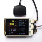
Some interesting applications
By having access to these data, an Arduino can store, compute and show the real-time vehicle status in any unique way you can think of. Here are some of my works done with Arduino and the OBD-II adapter.


FAQ
Q: What is this product used for?
A: The most straight-forward use of this product is for making Arduino possible to access vehicle data easily. The OBD-II data, together with other data from GPS or all kinds sensors, can be logged and stored on SD/TF card with Arduino and that makes an open-source vehicle data logger (check out the data logger kits). More extensively, many interesting interaction applications requiring car data can be made.
Q: How is the adapter powered?
A: The adapter gets power from the 12V DC output from the OBD-II port.
Q: Does my Arduino needs power from somewhere in the car?
A: The adapter provides regulated 5V or 3.3V DC output to provide power for Arduino via its power connector. Your Arduino can be powered by connecting the power connector (VCC/GND) to Arduino’s VCC and GND pins, so no extra power input is needed.
Q: Do I need a CAN bus shield to use with the adapter?
A: Definitely no. The adapter retrieves data from CAN bus, like a CAN bus shield does and convert the more complicated CAN bus interface to simple serial UART interface which Arduino and most embedded systems are easy to access. The data connection is provided by adapter’s data connector (Rx and Tx).
Q: How do I connect the adapter with my Arduino?
A: The adapter works with all models of Arduino with the dedicated Arduino library and is connected with Arduino by connecting adapter’s Tx to Arduino’s Rx (D0) and adapter’s Rx to Arduino’s Tx (D1). If you want to connect and disconnect the adapter with your Arduino effortlessly, it’s recommended to use a common I/O breakout shield or use an Arduino board with breakout pins for Rx/Tx/VCC/GND.
Q: Is the power provided by the adapter always available in car?
A: This depends on whether the OBD-II port of your car still has power after ignition is off. Actually it is so with most cars.
Q: What’s the maximum frequency of data polling?
A: The OBD-II PIDs are polled one after another. The time for a polling depends on the speed of car’s ECU computer and how busy the computer is in different status. With a typical modern car with CAN bus, the time can be as low as 10ms. In other word, up to 100 times of data polling can be done in one second.
Product Gallery


User Feedbacks
Just wanted to let you know that I got the adapter today and took it for a spin on the race car. Worked great out of the box!
Haven’t tried the accelerometer/gyro yet or the legacy protocols but will do that in a couple weeks.Thanks
Brian Calder @ Bluefire Racing
2005 Mustang GT
#404 NASA Texas American Iron
www.bluefireracing.com